Lakhovsky's multiple
Wave Oscillator, theory
|
|
|
|
|
"Lakhovsky's multiple Wave Oscillator, theory"
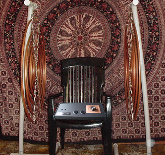
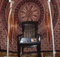
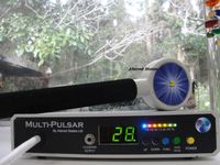
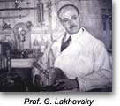
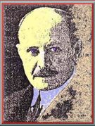
Georges Lakhovsky, THEORY The MWO was first brought out in the early 1930's by Lakhovsky who pointed out that all cells capable of reproduction contain in their neuclei filaments of highly conductive material surrounded by an insulating medium. This filament which may be the RNA-DNA complex is always in the form of a spiral or helix, in other words, a coil. Therefore each will react as a tuned circuit if it's resonant frequency can be approximated by an external oscillating coil. This will then raise the energy level and vitality of a marginal cell to normal levels. The MWO radiates a bandwidth of frequencies from the audio range to beyond microwave frequencies. The unit that I built was tested with a spectrum analyser and was found to have an output greater than 2000MHz, the limit of the measuring instrument. Thus whatever the resonant frequency of an individual cell of the body is tuned to, there will be a matching frequency produced by the MWO. The subject being treated sits between two antennaes for a period that Lakhovsky recommende of 15 minutes every four days for four treatments. It would appear that no increase in benefit is obtained from longer treatments.
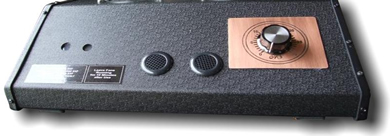
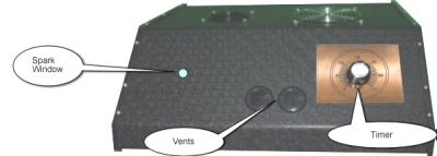
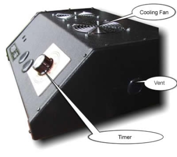
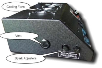
Design: The following design comes from a combination of the original Lakhovsky information, Bob Beck's (Borderland Science) modified version, and my own derivation using locally available parts. I attempted to keep the electrical parameters of my circuit close to the original, so as the original circuit used a "model T Ford" coil, I borrowed two of them to check out the frequency at which they vibrated. This turned out to be 166Hz, so that was the frequency that I set the oscillator to. Oscillator: The oscillator consists of a 4093 Schmidt trigger configured as an oscillator, followed by a buffer to drive the BC107 transistor. The frequency is set by the combination of the 4.7uF capacitor and the 10K trimpot. I found that the frequency stability of this circuit is better than using a 555 timer. The stability is maintained by using a LM340T voltage regulator to keep the supply voltage constant. High Voltage Circuit: The output of the oscillator is fed into a standard transistor ignition circuit which feeds a standard car coil to create a higher voltage. I decided that the easiest way of triggering the car coil was to use a standard transistor ignition circuit as this was a reasonably simple circuit, readily available and offerred excellent switching pulses to the coil, giving maximum possible output. The output of the car coil is fed into the primary side of the Tesla coil via two capacitors, each consisting of eight 0.01uF, 3KV rated capacitors connected in a series/parallel combination to achieve the required capacitance and voltage characteristics. (High voltage capacitors are pretty well impossible to obtain these days) The spark gap is made variable to enable the output voltage to be varied, the larger the gap, the higher the output volts. The secondary of the Tesla coil is connected to two antennae, one to each output lead. CONSTRUCTION Power Supply: The nominal 12 Volt supply can be provided by a conventional 240/12 Volt transformer with a diode bridge, filter capacitor and LM340T voltage regulator. The circuit needs to supply 2 Amps minimum. Another alternative is to use a 12 Volt battery and charger. Oscillator: This can be built on a Veroboard or similar to the constructors requirements. Transistor Ignition: This can either be built up on a Veroboard, similar to the oscillator circuit or it can be bought as a complete kit. (Jaycar, Dick Smith) The car coil can be obtained from any auto parts supplier. Use a 12 volt coil, one that is designed for use without a resistor. Spark Gap: This was made from two 10mm bolts with the heads machined to form two round buttons rather than hexagonal heads. These were then fitted to two supports, one moveable and one fixed to obtain adjustment of the gap. (See Fig 1)
High Voltage Capacitors: These eight capacitors were arranged to obtain the required capacitance and voltage ratings. (See Fig 2) Tesla Coil: Primary - This is wound on plastic water pipe as a former, approximately 63mm in diameter. The winding consists of 23 turns of #16 bars wire spaced out to approximately 75mm in length. Secondary - Wound on plastic water pipe as a former, approximately 32mm in diameter. This winding consists of 106mm length of winding, tightly wound using enamel coated copper wire. NOTE: It is imperative that the two coils are very well insulated from each other, otherwise sparks will track across between the coils and reduce the output considerably. A good method to check that this is not happening is to operate the device in the dark and check visually for any sparks or coronas. (See Fig 3) Antennae: This is the icky bit! There are various designs available, most of which come from the work done by the Borderland Sciences Research Foundation. These are available from various publications put out by them. The most common design can be constructed by gluing a piece of aluminium foil on a piece of 6mm plastic sheet. (approx 300mm X 300mm) A series of circles are then scribed through the foil to the plastic backing and every other ring is removed. This should leave 16 concentric rings of aluminium, ranging in size from 12mm to 270mm. A gap is then cut in each ring - note that the gaps are alternated 180 degrees for each consecutive ring. A wire is then inserted through the centre point of the antennae and this is where the Tesla coil is connected to it. (See Fig 4) The alternative, and I feel that it would work much better, is to use copper tubes bent to form the dipoles with copper balls formed and attached to the ends of them as per the original Lakhovsky design. (See Fig 5) NOTE: The antennae must be mounted on non conductive mounting brackets. Bruce T
MWO
|